


- Oxidation Industry solutions
- DE wall panel oxidation regeneration process flow
- DE wall panel oxidation regeneration process
- Service History
- Open Mask Industry Solutions
- Open Mask Operation process
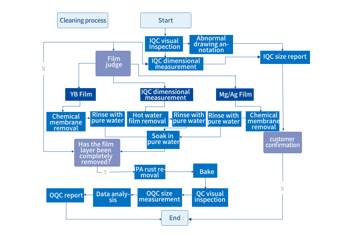
- QC Flow Chart
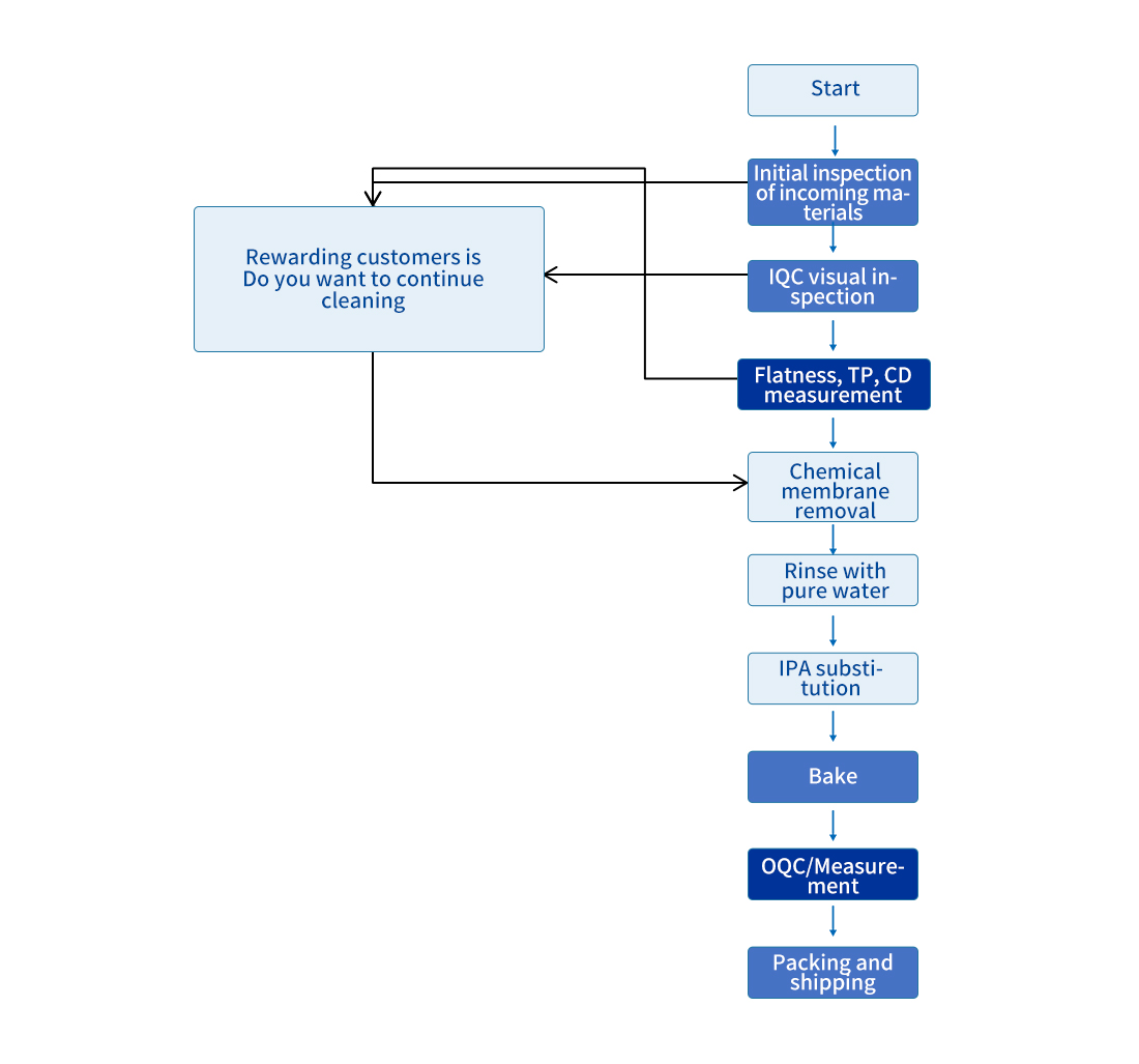
- Open Mask Cleaning Process Flow
- Open Mask Cleaning specifications
- Cleaning specifications
- Semiconductor Industry Solutions
- Photovoltaic cleaning and regeneration process flow - carrier board
- Process flow of semiconductor component cleaning and regeneration
- Ceramic Melting Industry Solutions
- DE Ceramic Component Cleaning and Regeneration Process Flow
- DE Ceramic Component Cleaning Process
- Service History
- Surface treatment process flow of components
- Introduction to Ceramic Melting and Spraying
- Ceramic melting business
- Product Display (Optoelectronics)
- Product Display (Semiconductor)
- Product Display (Semiconductor ESC)
- Ceramic melting technology module
- Ceramic melt blown derivative process (stripping technology)
- Ceramic melt blown derivative process (new oxidation process)
- Surface treatment process flow of components
- Performance testing of oxidation new process performance indicators
- Ceramic melt blown derivative process (cleaning and regeneration process)
- Surface treatment process flow of components
- leaning and regeneration technology capability
- Special product (power on processing)
- Service History
- Cleaning industry Solutions
- PVD component cleaning and regeneration process flow
- Service History
- CF component cleaning and regeneration process flow
- IMP cleaning process flow
- Service History
- Process flow for cleaning and regenerating inner lining components
- Service History
- Quality control capability
- Cleaning and regeneration technology capability
- Advantages of advanced process precision cleaning
- Photovoltaic cleaning and regeneration process flow - carrier board
- CVD Industry Solutions
- CVD component cleaning and regeneration process flow - Diffuser
- CVD component cleaning and regeneration process flow - Baking Plate
- CVD component cleaning and regeneration process flow 1-Susceptor
- CVD component cleaning and regeneration process flow 2-Susceptor
- CVD component cleaning and regeneration process flow - Shadow Frame
- Core technology
- Service History

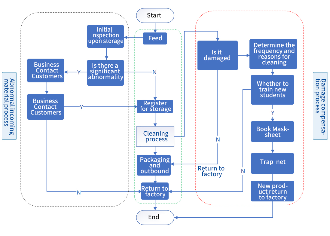
For Ag/MG/YB coating cleaning process and auxiliary trolley instructions
① IQC
Conduct a visual inspection of the incoming mask and record the entire inspection process to avoid inconsistent confirmation results between both parties.
Inspect the surface of the mask with strong light for any abnormalities such as folds, hits, scratches, or desoldering.
Check the surface of the mask in the darkroom for dirt and rust spots.
During the inspection process, annotate any abnormal issues with diagrams and send them to the customer via email for confirmation.
Perform TP and CD inspections on the surface of the mask, with 36 points each for TP and CD inspections.
② Chemical membrane removal
Chemical film removal: Move the mask to the automatic cleaning line and perform chemical soaking and DI pure water cleaning according to the programmed soaking time (pure water resistance value:> 10M Ω).
Chemical membrane removal lif: Soak in 60 degree hot DI pure water for 45 minutes, rinse twice with DI pure water, and then soak in a DI pure water tank for 15 minutes.
Chemical film removal - Mg/Ag: Use electronic grade hydrogen peroxide solution for chemical film removal, soak for 50 minutes, (detect the reaction status and concentration of the tank solution every 15 minutes).
③ Soak in pure water
Use ultrasonic oscillation to remove residual liquid and micro particles on the surface of the mask, ensuring a clean surface (power: 1200w, frequency: 40Hz, time: 15 minutes).
④ Rust prevention cleaning
Rinse the mask with IPA for at least 10 minutes after removing the film to ensure that there is no rust residue on the surface.
The lifting speed of the automatic cleaning line is 5mm/S, and the left and right movement speed is 10mm/S (the program can be set to manual or automatic).
⑤ Bake
Transport the mask to a specialized drying vehicle for surface inspection and confirmation, ensuring no water stains remain.
Check for any residual watermarks on the surface of the mask using a strong light in the darkroom. If there are watermarks, wipe them with pure water and then dry them with alcohol.
After fixing the mask, place it in a dedicated dust-free drying oven. During the drying process, do not open the oven. The drying temperature is 60 ± 1 ℃ and the drying time is 180 minutes.
After opening the drying oven, fill it with nitrogen to ensure a positive pressure of 5-10Mpa inside the oven.
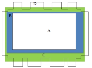
| Mask defect area and definition | |||||
| Serial Number | Region | Specification Description | Illustration | ||
| 1 | Adistinguish | Panel arrow key coating area |
|
||
| 2 | Bdistinguish | Align Mark and design marking area | |||
| 3 | Cdistinguish | Solder joint area | |||
| 4 | Ddistinguish | Frame area | |||
| Mask cleaning specifications | |||||
| No | Project | Description | Recycle front | Recycle after | notes |
| 1 | TP | <50um | <30um | <30um | / |
| 2 | CD | <50um | <30um | 1.<30um 2. Diff <10um |
/ |
| 3 | Flatness | <350um | TBD | 1.<250um 2. Diff< 50um |
/ |
| Serial Number | Defect | Describe | Before cleaning | After cleaning | |
| 1 | Fold injury | Not allowed | Not allowed | Not allowed | |
| 2 | Wound | Zone A: Not allowed Zone B: undefined Zone C: undefined Zone D: undefined |
Zone A: Not allowed Zone B: undefined Zone C: undefined Zone D: undefined |
Zone A: Not allowed Zone B: undefined Zone C: undefined Zone D: undefined |
|
| 3 | Rust | Not allowed | Allow cleaning | Not allowed | |
| 4 | Dirty | 1. Can clear the processor · not counted (air gun, alcohol wiping) 2. Uncleachable: A/B zone: Not allowed C/D zone: visually invisible |
1. Can clear the processor, not counting (air gun, alcohol wipe) 2. Uncleachable: A/B zone: not allowed C/D zone: visually invisible |
1. The processor can be cleared, excluding (air gun, alcohol wiping) 2. Uncleachable: A/B zone: not allowed C/D zone: visually invisible |
|
| 5 | Scratches | 1. Non sensory scratch: Depth ≤ 5um is considered non sensory scratch, not included | |||
| 2. Feeling scratched | |||||
| A leading global enterprise in clean production equipment services | OK | ||||
| 6 | Particle&Chemical Residue | 1. Can clear the processor · not counted (air gun, alcohol wiping) 2. Uncleachable: A/B zone: Not allowed A/B zone: not allowed C/D zone: visually invisible |
NA | 1. Can clear the processor · not counted (air gun, alcohol wiping) 2. Uncleachable: A/B zone: not allowed C/D zone: visually invisible |
|
| 7 | Solder joint | The solder joints must not have detachment | The solder joints must not have detachment | The solder joints must not have detachment | |
| 8 | TP point, Mark, etc. indicate that the opening is blocked | Zone A: Not allowed Zone B: Not allowed Zone C: Undefined Zone D: Undefined Zone | Zone A: Not allowed Zone B: Not allowed Zone C: Undefined Zone D: Undefined Zone | Zone A: Not allowed Zone B: Not allowed Zone C: Undefined Zone D: Undefined Zone | |
| 9 | Coating residue | Zone A: Not allowed Zone B: Not allowed Zone C: Undefined Zone D: Undefined Zone | NA | Zone A: Not allowed Zone B: Not allowed Zone C: Undefined Zone D: Undefined Zone | |

Phone: 021-59228356
Address: 1A301, Liandong U Valley, No. 405 Tuoqing Road, Qingpu District, Shanghai


Copyright: Yingyou Optoelectronics Technology Group Co., Ltd. Anhui ICP Registration No. 00000000 Disclaimer
Technical Support: NetEase Technology